|
For Danish version, click here.
In this tutorial you learn how to use the Eclipse Modeling Framework
(EMF) to generate a simple editor for a model of some domain. In our
example, the domain will be Petri nets. Moreover, you learn how to
extend the generated editor with some additional functionality. In
our example, this will be a simple action for firing enabled transitions
of the Petri net.
Note that the solution in the first assignment will be very simplistic
and, in some cases, even abuse of the technology. We will fix these issues
in one of the next assignments. Moreover, we will create a nicer editor
for graphically editing Petri nets in later tutorials.
You will learn how to:
- install (the correct version) of Eclipse with the Eclipse Modeling Tools extension,
- create EMF projects,
- create Ecore/EMF models,
- generate code from such models, and how to
- use the generated code.
Below, the assignment is broken down to simple steps.
- Install Eclipse Mars (4.5) with the Eclipse Modeling Tools extension:
- Download Eclipse with the Eclipse Modeling Tools extension from
http://www.eclipse.org/downloads/packages/eclipse-modeling-tools/marsr
for your computer and platform.
- Extract the downloaded file to a folder on your computer. The
folder to which you extracted the downloaded file contains an
executable file with name "eclipse".
- Start your newly installed version of Eclipse by executing
this "eclipse" file.
- The first time you start this new version of Eclipse, you will
be asked to choose a folder for the Eclipse you would like to
place your Eclipse projects in.
- In your new workspace, create a new EMF project, which you will use
for creating a model for Petri nets. Choose a reasonable name
for this project, which could, for example, be
mbse.f16.tutorial1:
- If your Eclipse is not in the "Plug-in Development" perspective already,
you should switch to it by chosing
Window -> Perspektive -> Open Perspektive -> Other...
- Create a new empty EMF project in your Eclipse workspace:
select [File ->] New -> Project and then choose
"Empty EMF Projekt" from category "Eclipse Modeling Framework".
- In the folder "model" of this new project, create a new Ecore file:
- Select the folder "model" in your new EMF project and create
a new Ecore file: choose New -> Other... and then choose
"Ecore Model" from category "Eclipse Modeling Framework"; when
asked for the "Model Object" select the default, which is "EPackage";
then follow through the dialogs.
- After following through the creation wizard, the created file should
automatically open in the "Sample Ecore Model Editor". If the file
does not open automatically, you can open the file by right-clicking the
the file and then selecting: Open With ->
Sample Ecore Model Editor.
- Select the element package at the top of the file element and then,
in the "Properties" view of the Eclipse IDE, add a name for the package
(e.g. "petrinet"), and add a "Ns Prefix" (e.g. "pn") and a "Ns URI"
(e.g. "http://mbse-f16/tutorial1/petrinet"). At last save the file.
Note: If the "Properties" view is not open, you can open it
by either selecting an element and right-clicking it, and then
chosing "Show Properties View"; or you can use
Windows -> Show View -> Properties.
- Continue using the editor for the Ecore file to add the classes and associations
(in Ecore, associations are called references) which reflect a model of Petri nets:
- Later, we will use a graphical editor for creating Ecore models.
For now, we stick with the simple Ecore tree-editor. You can
add a class by right-clicking on the package element at the top
of the file, and then chosing "New Child -> EClass". For adding
attributes to a class, you can right-click this class and choose
"New Child -> EAttribute"; in a similar way, you can add a reference
from one class to another.
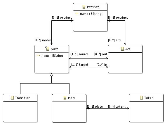
As a model for Petri nets, you can use the one from Lecture 1, or
you can use the one below:
Note: The cardinality "*" / "many" of a reference is represented by
a "-1" as "Upper Bound" (and "0" as "Lower Bound").
- Note that it will be necessary for this task that your model
does not only have references
source and target
from the Arc to Node, but you will
also need references in the opposite direction from Node
to Arc, which represent the
incoming and outgoing arcs of a Node.
In EMF/Ecore, you can make two references opposites of each
other by chosing one of them, and then, in the "Properties" view,
selecting the opposite reference as the "Opposite".
- In order to make sure that a Petrinet object can contain elements,
you need to make sure that the reference from
Petrinet
to Node and Arc are compositions
(the attribut "Containment" of these references should be set to
"true", which can be done in the "Properties" view).
- At last you should check that your Ecore/EMF file is correct:
You can check that by validating your model. To this end,
right-click on the package "petrinet" of your model, and select
"Validate". If any errors are reported, fix them before you continue
with the next steps.
- When your model is complete (and validated), generate code from it:
- The first step to generating code is to generate a so-called
"Gen Model". To this end, select the Ecore file with your
Petri net model, right-click on it and choose
New -> Other...; then select "EMF Generator Model" from category
"Eclipse Modeling Framework". The "Gen Model" file should have the
same name as the Ecore file, but with file extension ".genmodel".
- Open this "Gen model" file. There is only one thing you should
change in that file for now: this is the attribute
"Base Package" on the package itself. It defines the Java package
to which the code of the model will be generated; this
could for example be
mbse.tutorial1. After you have
added the attribute "Base Package", save the "Gen model" file.
- Now, by right-clicking on the package element of the "Gen model" file,
and by chosing "Generate all", you can generate the code from your model
(for now, generating the
"Model code", the
"Edit code" and the "Editor code" would be enough).
- If the code generation is successful, you should have three new
plugin projects in your workspace, which compile and build automatically,
and there should be no errors in these projects. If there are errors,
your Ecore model or the "Gen model" file, probably contain some errors,
which need to be fixed.
- If the code generation is successful, you can check whether
the generated editor for Petri nets actually works. You do this by
starting another instance of Eclipse, the so-called runtime-workbench
(by contrast to the Eclipse workbench
you have been working in up to now, which is the development workbench):
- The first time you start up a new runtime workbench, you need to
create a new "Run configuration":
choose the "Run" symbol in the toolbar and select "Run configuration",
which starts a "Create, manage and run configurations" dialog;
in this dialog, choose
"Eclipse Application" and click on "New launch configuration";
enter a name for this configuration (e.g. MBSE Tutorials), and then
click on "Apply" or "Run". After some time, a new instance of
Eclipse should start up (the runtime workbench) — in this
instance, your newly generated plugins are installed and running,
so your generated Petrinet editor should be ready for use there.
Note that when you want to start up a runtime workbench the next time,
you can just click on the "Launch" button.
- In the runtime workbench, create a new project (this can be
a simple "Project" from category "General"). In this new
project, create a new file for Petri nets by
[File ->] New -> Others... and then by selecting "Petrinet Model"
in category "Example EMF Model Creation Wizard"; choose a file
name and when asked select "Petrinet" as the "Model Object".
- In the editor which opens, you should see a tree with a
"Petrinet" as top-level element. By right-clicking on it and
then selecting "New Child", you can add different elements
to the Petri net: places, transitions and arcs (if you also
can add "Nodes", you should make the class Node abstract in your model).
You can connect places and transitions to arcs by editing the
source and target attributes of the arcs in the "Properties" view.
Note: If the "New Child" menu on s Petrinet element in the editor
does not work,
you probably have forgotten to make the references from
the Petri net class to nodes and arcs compositions.
- If the editor works as expected, you can shut down the runtime workbench
of Eclipse. You are ready for the last step of this tutorial: Implementing
a function which simulates a Petri net; you should add a popup menu
on transitions to the Petri net editor, which will fire the selected
transition, if it is enabled. Most of the code necessary for installing
this button is prepared for you already. You just need to add some
code to two methods, which check the enabledness of a transition,
and performs the firing.
- Download the Eclipse project file from
MDSU-tutorial1-simulator.zip and save it somewhere on your computer.
Import the project from this file by chosing File -> Import; then
select "Existing Projects into Workspace" from category "General" and
click "Next"; then select the file that you have downloaded,
select "dk.dtu.compute.se.mdsu.tutorial1.simulatorX" and follow through
the dialog.
- This project should now be in your workspace. You need to open
plugin.xml in order to fix some problems. In tab
"Dependencies" delete the reference to the non-existing project,
and instead add your first EMF project (the one with the EMF model
for Petri nets). You also need to replace one reference to the
the actual Transition class, which was generated from your model.
The easiest way to do that is in the textual representation of
the plugin by chosing the tab "plugin.xml". In that text, find
the XML attribute type referring to dk.dtu.compute.se.mdsu.petrinet.Transition and replace it
with the fully qualified name of your class (actually interface)
Transition.
- At last, you need to implement the methods
isEnabled()
and fire() of class SimulatorCommandHandler:
The first method should check, for a given
transition, whether it is enabled: for each incoming arc of the
transition, there should be one token available at the
source place of that arc. The second method should fire a transition:
for a given
transition, remove one token from each source place for each
incoming arc and add one to each target plae of each outgoing arc.
- Check whether your simulator works properly. To this end, you need to
start the Eclipse runtime workbench again. In the runtime workbench
open a Petri net file (and maybe edit it). Now, if you right-click
on a transition, a popup menu should open with an entry "MDSU Tutorials",
which has
a subentry "Fire Transition"; this action should be enabled, if
the selected transition is enabled, and disabled otherwise. If you
click the "Fire Transition" action, the transition should actually
fire (removing and adding the tokens in the corresponding places);
and you should see the changes in the editor.
Note: Due to some Eclipse internal issues (lazy initialization of
handlers for popup menus), the first "Fire Transition" is always
enabled. Only after you clicked it once, the status of the
"Fire Transition" entry is shown correctly.
- Graphically editing EMF models:
It is also possible to edit EMF/Ecore models graphically, for exampe by
using EcoreTools. We will start using this graphical editor from next
week. If you are interested in using EcoreTools, you can read a bit
about that on http://www.eclipse.org/ecoretools/doc/.
|